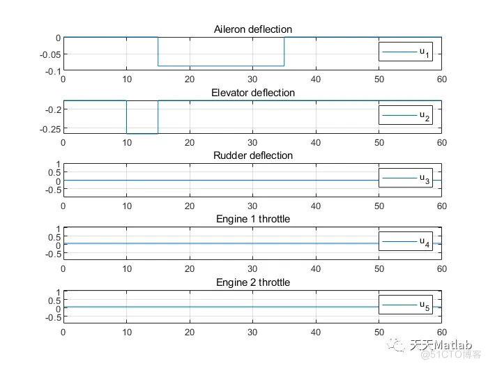
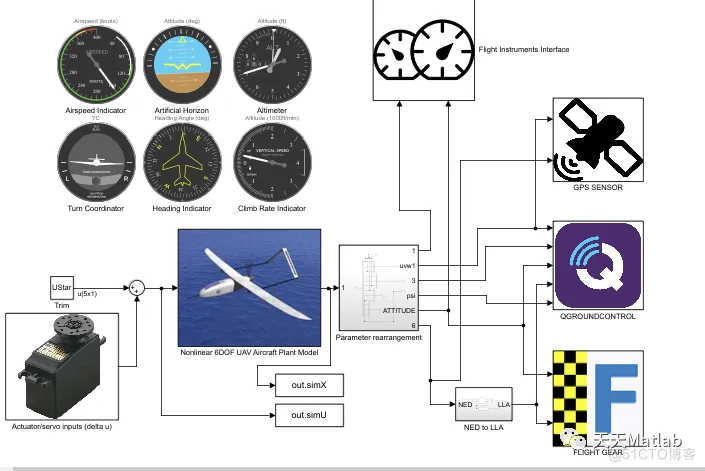
在真实的三维虚拟环境中进行飞行测试越来越被认为是评估飞机模型及其控制系统的安全且经济有效的方法。本文首先回顾并比较了迄今为止已成功与 MathWorks 软件接口的最流行的基于个人计算机的飞行模拟器。这种协同仿真方法可以将 Matlab 工具箱的导航、控制和传感器建模等功能的优势与专用飞行仿真软件的高级仿真和场景渲染功能相结合。然后,该方法可用于验证飞机模型、控制算法、飞行处理特性,或根据飞行数据进行模型识别。然而,有 缺乏足够详细的分步飞行协同仿真教程,而且也很少尝试一次评估一种以上的飞行协同仿真方法。因此,我们使用 Simulink 和三种不同的飞行模拟器演示我们自己的分步联合仿真实现:Xplane、FlightGear 和 Alphalink 的虚拟飞行测试环境 (VFTE)。所有三种联合模拟均采用实时用户数据报协议 (UDP) 进行数据通信,每种方法都具有优势,具体取决于飞机类型。以 Cessna-172 通用航空飞机为例,Simulink 与 Xplane 的联合仿真展示了成功的虚拟飞行测试,能够准确地同时跟踪高度和速度参考变化,同时在任意风力条件下保持滚转稳定性,这对单螺旋桨塞斯纳提出了挑战。对于中等续航能力的 Rascal-110 无人机 (UAV),Simulink 使用 MAVlink 协议与 FlightGear 和 QGroundControl 连接,允许准确跟踪地图上的横向 UAV 路径,此设置用于评估基于Matlab的六自由度无人机模型。对于较小的 ZOHD Nano Talon 微型飞行器 (MAV),Simulink 与专为此 MAV 设计的 VFTE 接口,并与 QGroundControl 一起使用软件在环 (SIL) 模拟来测试先进的基于 H-infinity 观察器的自动驾驶仪,以在有风条件下实现稳健的低空飞行。然后最终使用控制器局域网 (CAN) 数据总线和带有模拟传感器模型的 Pixhawk-4 迷你自动驾驶仪扩展到 Nano Talon MAV 上的硬件在环 (HIL) 实施。
function XDOT = UAV_model(X, U)
%UAV_MODEL Full 9 DOF model for the UAV based on the RCAM Aircraft
%(Christopher Lum, Garteur)
%   [XDOT] = UAV_MODEL(X,U) returns the longitudinal state
%   derivatives, XDOT, given the current state and inputs, X and U.  The
%   constants are the nominal values defining the aircraft specifications.

%============UAV State========%
x1 = X(1);  %u
x2 = X(2);  %v
x3 = X(3);  %w
x4 = X(4);  %p
x5 = X(5);  %q
x6 = X(6);  %r
x7 = X(7);  %phi
x8 = X(8);  %theta
x9 = X(9);  %psi

u1 = U(1);  %d_A aileron
u2 = U(2);  %d_T elevator
u3 = U(3);  %d_R rudder
u4 = U(4);  %d_th1 throttle 1
u5 = U(5);  %d_th2 throttle 2

%============Constants=========%
%nominal UAV constants
m = 120000; %aircraft mass (kg)

%Aero
cbar = 6.6; %Mean aerodynamic chord (m)
lt = 24.8;  %distance by AC of tail and fuselage (m)
S = 260;    %Wing planform area (m^2)
St = 64;    %Tail planform area (m^2)

Xcg = 0.23*cbar;                %x position of CoG in Fm (m)
Ycg = 0;                        %y position of CoG in Fm (m)
Zcg = 0.10*cbar;                %z position of CoG in Fm (m)

Xac = 0.12*cbar;                %x position of aerodynamic center in Fm (m)
Yac = 0;                        %y position of aerodynamic center in Fm (m)
Zac = 0;                        %z position of aerodynamic center in Fm (m)

%Propulsion constants
Umax  = 120000*9.81; %  max thrust in newtons
Xapt1 = 0;           %x position of engine 1 force
Yapt1 = -7.94;       %y position of engine 1 force
Zapt1 = -1.9;        %z position of engine 1 force

Xapt2 = 0;           %x position of engine 2 force
Yapt2 = 7.94;        %y position of engine 2 force
Zapt2 = -1.9;        %z position of engine 2 force

%Miscellaneous constants
rho = 1.225;        %air density (kg/m^3)
g = 9.81;           %gravitational acceleration (m/s^2)
depsda = 0.25;      %change in downwash (rad/rad)
alpha_L0 = -11.5*(pi/180);    %zero lift AoA (rad)
n = 5.5;            %slope of linear region of lift slope
a3 = -768.5;        %coef of alpha^3
a2 = 609.2;         %coef of alpha^2
a1 = -155.2;        %coef of alpha^1
a0 = 15.2;        %coef of alpha^0
alpha_switch = 14.5*(pi/180);

%=======Control limits and Saturation=======%
%can be changed in simulink
%{
u1min = -25*pi/180; %Ailerons limits
u1max = 25*pi/180;

u2min = -25*pi/180; %Elevator limits
u2max = 10*pi/180;

u3min = -30*pi/180; % Rudder limits
u3max = 30*pi/180;

u4min = 0.5*pi/180; % Throttle 1 limits
u4max = 10*pi/180;

u5min = 0.5*pi/180; % Throttle 2 limits
u5max = 10*pi/180;
%}
%Saturation
%{
if(u1>u1max)
    u1 = u1max;
elseif(u1<u1min)
    u1 = u1min;
end

if(u2>u2max)
    u2 = u2max;
elseif(u2<u2min)
    u2 = u2min;
end

if(u3>u3max)
    u3 = u3max;
elseif(u3<u3min)
    u3 = u3min;
end

if(u4>u4max)
    u4 = u4max;
elseif(u4<u4min)
    u4 = u4min;
end

if(u5>u5max)
    u5 = u5max;
elseif(u5<u5min)
    u5= u5min;
end
%}

%===========Intermediate Variables==========%
%airspeed
Va = sqrt(x1^2 + x2^2 + x3^2);

%alpha and beta
alpha = atan2(x3,x1);%Angle of attack
beta = asin(x2/Va);%Side slip

%dynamic pressure
Q = 0.5*rho*Va^2;

%define the vectors wbe_b and V_b
wbe_b = [x4;x5;x6];
V_b = [x1;x2;x3];

%============Aerodynamics==================%
%Calculate the CL_wb
if alpha<=alpha_switch
    CL_wb = n*(alpha - alpha_L0);
else
    CL_wb = a3*alpha^3 + a2*alpha^2 + a1*alpha + a0;
end

%Calculate CL_t
epsilon = depsda*(alpha - alpha_L0);
alpha_t = alpha - epsilon + u2 + 1.3*x5*lt/Va;
CL_t = 3.1*(St/S)*alpha_t;

%Total lift
CL = CL_wb + CL_t;

%Total drag  (no tail)
CD =  0.13 + 0.07*(5.5*alpha + 0.654)^2;

%Sideforce
CY = -1.6*beta + 0.24*u3;

%==========Dimensional Aerodynamic Forces======%
%calculate dimensional forces in F_s stability axis
FA_s = [-CD*Q*S;
         CY*Q*S;
        -CL*Q*S];

%Rotate the forces to F_b body axis
C_bs = [cos(alpha) 0 -sin(alpha);
        0 1 0;
        sin(alpha) 0 cos(alpha)];

FA_b = C_bs*FA_s;

%========Aerodynamic Moment coefficient about AC ========
%Calculate moments in Fb
eta11 = -1.4*beta;
eta21 = -0.59 - (3.1*(St*lt)/(S*cbar))*(alpha - epsilon);
eta31 = (1 - alpha*(180/(15*pi)))*beta;

eta = [eta11;
       eta21;
       eta31];

dCMdx = (cbar/Va)*[-11 0 5;
                    0 (-4.03*(St*lt^2)/(S*cbar^2)) 0;
                    1.7 0 -11.5];

dCMdu = [-0.6 0 0.22;
          0 (-3.1*(St*lt)/(S*cbar)) 0;
          0 0 -0.63];

%Calculate CM about AC in Fb axis
CMac_b = eta + dCMdx*wbe_b + dCMdu*[u1;u2;u3];

%========Aero Moment About AC==========
%normalize to an aerodynamic moment
MAac_b = CMac_b*Q*S*cbar;

%conversion to stability axis
C_sb = C_bs';
Mac_b = CMac_b*Q*S*cbar;
Mac_s = C_sb*Mac_b;
CMac_s = Mac_s./(Q*S*cbar);
CMac_s = C_sb*CMac_b;

%========Aero Moment About CG==========%
%transfer moment to CG
rcg_b = [Xcg;Ycg;Zcg];
rac_b = [Xac;Yac;Zac];
MAcg_b = C_bs*Mac_s + cross(FA_b,rcg_b - rac_b);

%=========Engine Force and moment======%
%Thrust
F1 = u4*Umax;
F2 = u5*Umax;

%Assume thrust aligned with Fb
FE1_b = [F1;0;0];
FE2_b = [F2;0;0];

FE_b = FE1_b + FE2_b;

%Engine thrust offset from CoG.
mew1 = [Xcg - Xapt1;
        Yapt1 - Ycg;
        Zcg - Zapt1];

mew2 = [Xcg - Xapt2;
        Yapt2 - Ycg;
        Zcg - Zapt2];


MEcg1_b = cross(mew1,FE1_b);
MEcg2_b = cross(mew2,FE2_b);

MEcg_b = MEcg1_b + MEcg2_b;

%=============Gravity Effects=========%
%Calculating grabitational forces in the body frame. No moment about CoG
g_b = [-g*sin(x8);
        g*cos(x8)*sin(x7);
        g*cos(x8)*cos(x7)];

Fg_b = m*g_b;

%============State Derivatives==========%
%Matrix of Inertia
Ib = m*[40.07 0 -2.0923;
        0 64 0;
        -2.0923 0 99.92];

%Inverse of inertia matrix
invIb = (1/m)*[0.0249836 0 0.000523151;
               0 0.015625 0;
               0.000523151 0 0.010019];

%Form F_b (all the forces in Fb) and calculate udot, vdot, wdot
F_b = Fg_b + FE_b + FA_b;
x1to3dot = (1/m)*F_b - cross(wbe_b,V_b);

%Form Mcg_b (all moments about CoG in Fb) and calculate pdot, qdot, rdot.
Mcg_b = MAcg_b + MEcg_b;
x4to6dot = invIb*(Mcg_b - cross(wbe_b,Ib*wbe_b));

%Calculate phidot,thetadot, and psidot
H_phi = [1 sin(x7)*tan(x8) cos(x7)*tan(x8);
         0 cos(x7) -sin(x7);
         0 sin(x7)/cos(x8) cos(x7)/cos(x8)];

x7to9dot = H_phi*wbe_b;

%Place in first order form


%Navigation Equations

C1v = [cos(x9) sin(x9) 0;
    -sin(x9) cos(x9) 0;
    0 0 1];

C21 = [cos(x8) 0 -sin(x8);
    0 1 0;
    sin(x8) 0 cos(x8)];
Cb2 = [1 0 0;
    0 cos(x7) sin(x7)
    0 -sin(x7) cos(x7)];
Cbv =Cb2*C21*C1v;
Cvb = Cbv';

x10to12dot = Cvb*V_b;

XDOT = [x1to3dot;
        x4to6dot;
        x7to9dot;
       x10to12dot];


免责声明:本文系网络转载或改编,未找到原创作者,版权归原作者所有。如涉及版权,请联系删