为了实现自动化的建模、画网格,也为了能给openfoam输出大量的网格,我又不想学习Gmesh等工具,所以花了两天时间,研究了以下ICEMCFD网格的脚本实现。
ANSYS ICEM CFD的脚本语言采用Tcl/Tk shell。大多数命令以“ic”开头,代表ANSYS ICEM CFD命令。
Tcl代表Tool CommandLanguage,是一种基于字符的编程语言。
Tk代表Toolkit,包含允许制作应用程序的图形界面或窗口的附加Tcl命令。
命令的基本形式:
command arg1arg2 arg3……
用换行符或分号结束;
用空格分割变量;
用行末尾的\表示续行,或者在变量组开头用{或“。
From the Replay control window - By using Do one or Do all
Using the File > Replay Scripts > Run from script file option
source - Using the Tcl command to execute Tcl commands in a file.
icemcfd -script - Specifying a script to run when you start up ANSYSICEM CFD
以上4种方式都可以在GUI下运行,但是只有最后两种才能在batch模式下运行。
在message window中运行source D:/user/script.tcl
以batch模式运行ANSYS ICEM CFD,在ANSYS ICEM CFD启动命令中加入-batch即可:icemcfd -batch-script D:/user/script.tcl
在脚本末尾加入exit,即可。
1. ic_uns_create_selection_subset 0
2. ic_uns_subset_add_region uns_sel_8 {0 0-0.5} {0 40 0.5} 0 2
3. ic_uns_set_part uns_sel_8 IN
4. ic_uns_subset_configure uns_sel_8 -width 0
5. ic_uns_subset_delete uns_sel_8
6. ic_delete_empty_parts
ic_uns_create_selection_subset 0:产生一个临时选择集,它不会出现在subset列表中。
ic_uns_subset_add_regionuns_sel_6 {0 0 -0.5} {0 40 0.5} 0 2:在一个region中增加单元,ic_uns_subset_add_regionname p1 p2 part dims [0 1 2 3]。
ic_uns_set_partname newpart:将entities从一个part移到另一个part。
ic_delete_empty_parts:删除part
ICEM CFD中没有直接的按柱坐标选择单元的选项,但可以利用其create part near position或者create part inregion并联合for循环,可以实现按柱坐标选择单元的目的。
我们的研究对象如下图所示,需要选择圆柱面,其中在画网格时,圆柱面周向的网格尺寸为0.005m。
for {set i 0}{$i<$nPoint } {incr i} {\
mess "thepoint is $i\n";\
set alpha [expr{2.0*$pi/$nPoint}];\
set x [expr{$x0+$R*cos($alpha*$i)}];\
set y [expr{$y0+$R*sin($alpha*$i)}];\
set z $z0;\
}
(1) ic_uns_subset_add_near_pos后面的坐标值要写成"$x $y$z"的形式,不可以为默认的ic_uns_subset_add_region uns_sel_0 {0 0 -0.5} {50 0 0.5} 0 2
(2) 在选择单元命令前,必须要有ic_uns_create_selection_subset0,其用意是建立一个临时的选择集。
(3) for循环里的命令须为一行,所以里面的每个命令后面都用“\”连接符。
(4) for循环非常慢,比手动选要慢许多。
ic_uns_create_selection_subset color_first_different color [""]
ic_uns_create_selection_edgelist on:Createsor deletes a temporary edge list for selection (depending onwhether on is 1 or 0).
ic_uns_subset_make_families name fams:Makes the currentsubset a family subset.
ic_uns_subset_add_families_and_types name fams types:Makes the currentsubset have a certain set of families and types.
ic_uns_subset_add_from dest src:Adds entities fromone subset to another.
脚本需要具有以下功能:
读入几何→网格划分设置→网格边界的part建立→保存projet→导出mesh文件
###设置变量
set wdirH:/FEI/meshStudy/case0Script
set caseNamecase0Script
#打开几何
ic_load_tetin$wdir/Geo0.tin
……
#mesh全局变量设置
……
#mesh各个部件网格设置
ic_geo_set_family_paramsCYLINDER_L prism 1 emax 0.005 ehgt 0.001 hrat 1.1 nlay 15 ewid 0 emin 0.0 edev0.0 prism_height_limit 0 law 1
……
#面网格划分设置
……
ic_set_meshing_paramssurface srf.00 etyp 0
#画面网格
ic_quad2 ……
……
#拉伸网格
……
ic_extrude mapuns_sel_0 numlayers 1 dir {0 0 -1} space 1 …… spacing_transl_rot 0.0 project 0
……
#规则网格边界选择,建立part---createpart in region
ic_uns_subset_add_regionuns_sel_0 {0 0 -0.5} {0 40 0.5} 0 2
……
#圆柱网格边界选择,建立part---createpart near position
……
for {set i 0}{$i<$nPoint } {incr i} {\
mess "thepoint is $i\n";\
set alpha [expr{2.0*$pi/$nPoint}];\
set x [expr{$x0+$R*cos($alpha*$i)}];\
set y [expr{$y0+$R*sin($alpha*$i)}];\
set z $z0;\
……
ic_uns_set_partuns_sel_0 CYLINDER;\
……
}
……
#保存project,导出网格
……
ic_save_project_file$wdir/$caseName.prj {……}
……
ic_exec{C:/Program Files/ANSYS……$caseName.fbc ./$caseName
……
exit
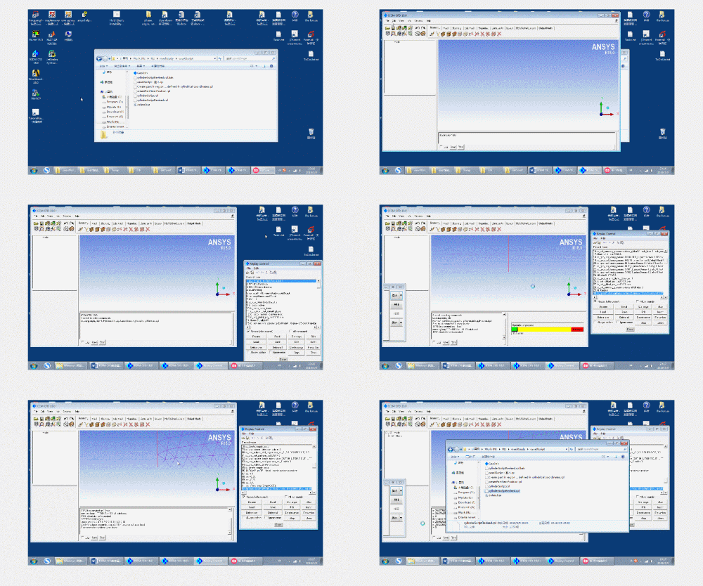
这里为了快速出结果,对圆柱周向的点取得比较稀疏,所以建立的圆柱part有缝隙,如下图所示。
总体效果见后面动图。

免责声明:本文系网络转载或改编,未找到原创作者,版权归原作者所有。如涉及版权,请联系删