PLC和HMI的仿真联调环境实现了闭环控制回路中人机界面和控制器部分的仿真功能。
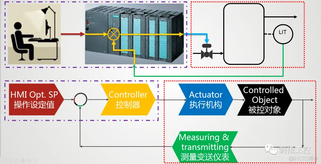
The Controlled Object and Measuring & Transmitting part also could be simulated through the PLC programming.
被控对象和测量变送环节同样可以通过PLC编程进行仿真。
Ps. Ignore actuator
此处忽略执行机构。
Controlled Object and Close Control Loop principle: 被控对象及闭环回路仿真原理
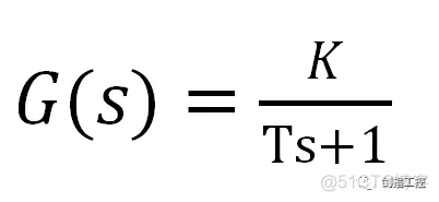
1.As we know, we usually use the Transfer Function to describe the Controlled Object. Using the single water tank as an example, the transfer function is
众所周知,我们通常使用传递函数来描述被控对象。以单容水箱为例,传递函数为
2.We also know that the PID Controller‘s time domain function is
我们同样知道PID控制器的时域函数为

Laplace transform to get the transfer function as below
拉普拉斯变换得到传递函数如下
.png)
3. In the PLC program, we could set the PID function block to make it become an Integrating Element.
在PLC程序当中,我们可以通过设定PID功能块,使之变成一个积分环节。
Set the , disable the Proportion function, and link the “output” to “input” to constitute a self-feedback loop.
设定 ,禁用比例功能,并将“输出”连回到“输入”构成自反馈回路。
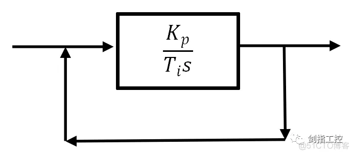
Base on the block diagram transform principle get the new transfer function, an inertial element (First-order process)
由方框图变换法则得到新的传递函数, 一个惯性环节(一阶环节)

4.From this, we could build a whole feedback control loop with “Controlled Object”.
由此,我们可以在PLC当中构建一个完整的带有“被控对象”的反馈控制回路。
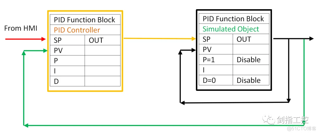
PLC programming: PLC编程
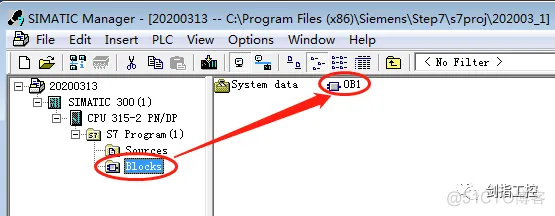
1.Open the “SIMATIC Manager” software, create a new project and finish the Hardware configuration.
打开编程软件,新建项目并完成硬件组态;
2.Double Click “OB1” to start programming
双击 “OB1”进入编程界面;
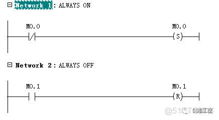
3.Insert the Open Contact/Close Contact and Set Coil/Reset Coil to make the “ALWAYS ON” and “ALWAYS OFF” constant for further using.
插入常开、常闭触点和置位、复位线圈来制作常开、常闭静态常量以备后用。
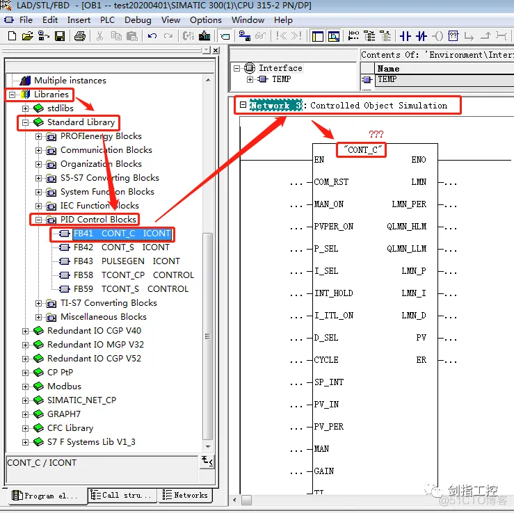
4.Unfold the tree structure of “Libraries” → “Standard Library” →”PID Control Blocks”, find the “FB41 CONT_C ICONT” and put to “Network 3”
展开“Libraries”的树状结构→ “Standard Library” → “PID Control Blocks”,找到“FB41 CONT_C ICONT”并拖拽到“程序段3”;
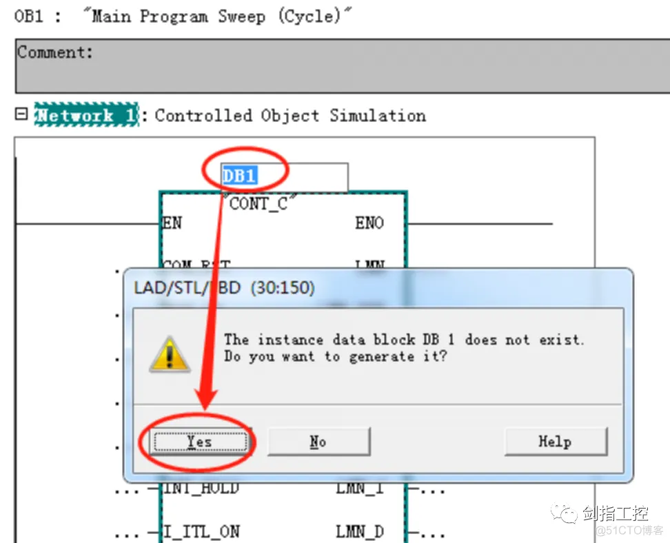
5.Create the corresponding Instance DB for these FB
为此功能块创建相对应的数据块;
6.Set the related parameters for FB;
为功能块设定相关参数;
Transfer the output back to input by using “MOVE”
通过“MOVE”指令将输出传递回输入
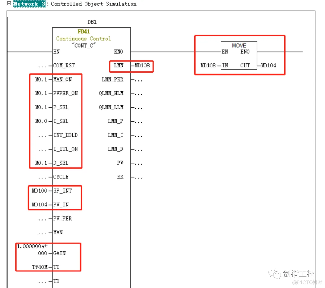
7.Create the “Network 4”, insert another “FB41” from “FB blocks”, assign “DB2” and set the related parameters or address;
新建“程序段4”,从“FB blocks”中再插入一个“FB41”为之分配“DB2”并设定相关参数或地址;
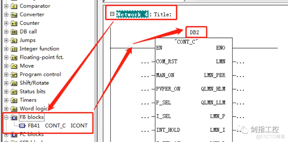
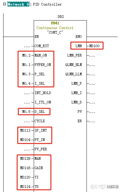
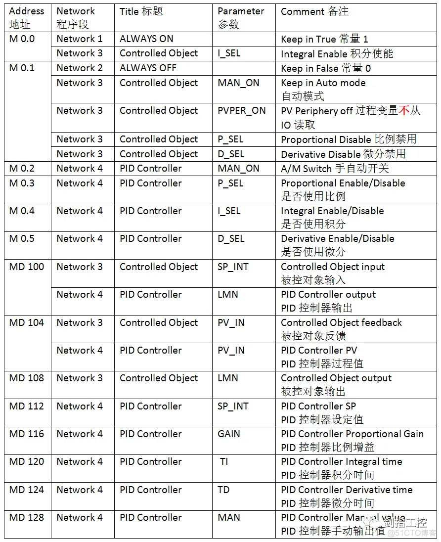
8.Related Parameter and Address reference as below:
相关地址参数参照如下:
HMI Touch Screen configuration and joint simulation: HMI触摸屏组态及联合仿真
1.Open the “TIA Portal” software and Create a new project, add the HMI device and configure the communication with PLCSIM
打开“TIA Portal”软件并创建新项目,添加HMI设备并组态与PLCSIM的通讯连接;
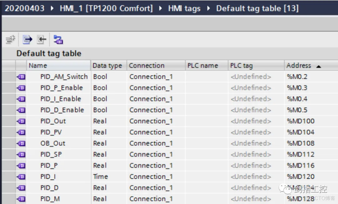
2.Create the tags in “Default tag table”, and set the related parameters and address;
在“默认变量表”中新建变量并设置相关参数和地址;
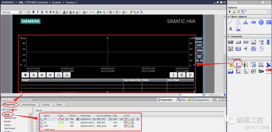
3.Inert the “Trend View” Controls, add the trend set the related properties.
插入“趋势”控件,添加趋势并设置相关属性。

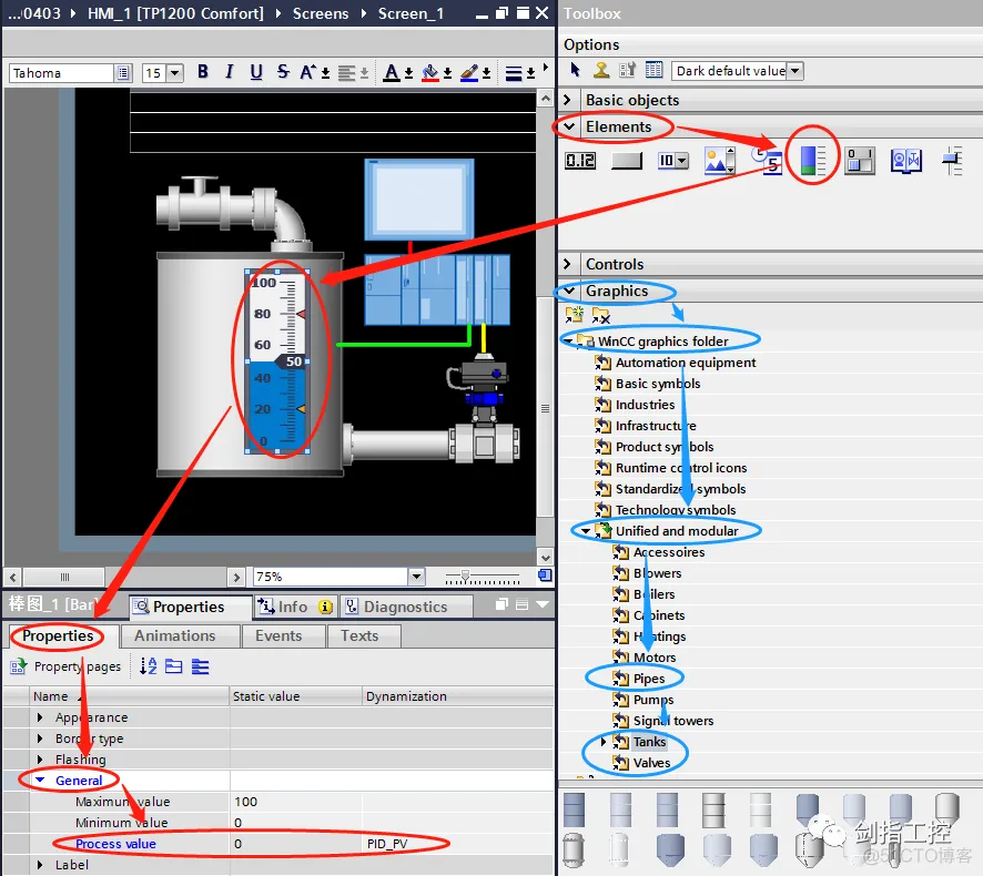
4.Inert the “Bar” Elements and static Graphics, set the related properties.;
插入“棒图”元素以及静态图形,并设置相关属性;
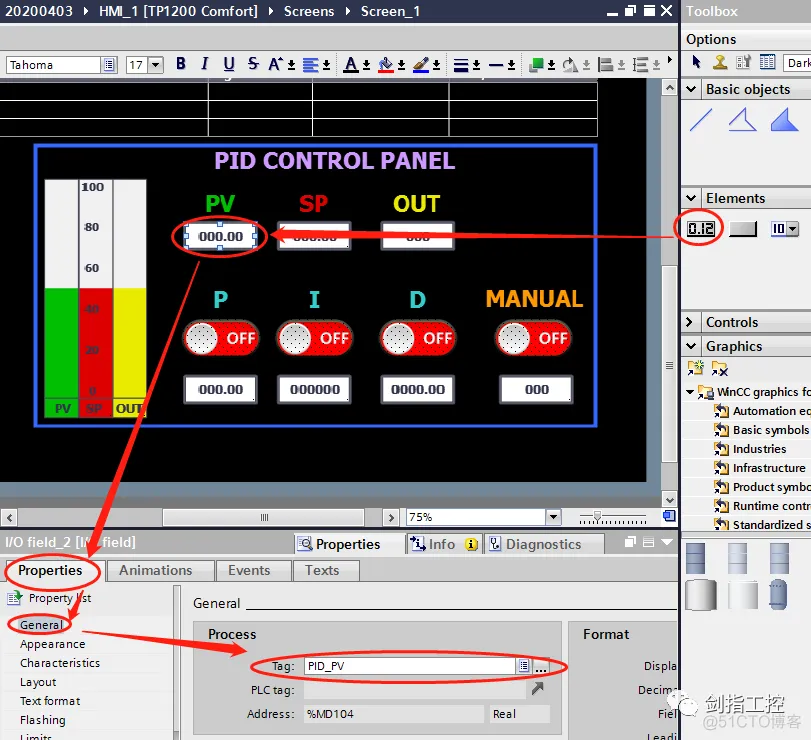
5.Inert the “I/O field” Elements, set the related properties.;
插入“IO域”元素,并设置相关属性;
6.Regarding the “P, I, D, Manual Switch” element, which consists of three parts.
关于“P、I、D、手自动开关”元素,它由三个部分组成;
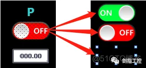
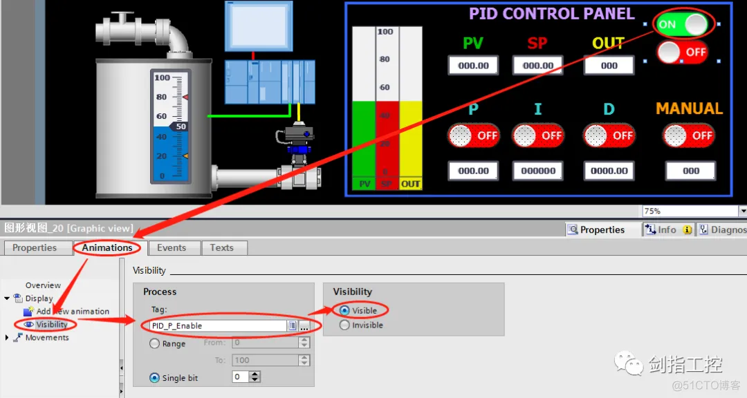
“ON” and “OFF” graph with the tag status related with “Visibility” animation;
“ON”和“OFF”图形以“可见性”动画关联标签状态;
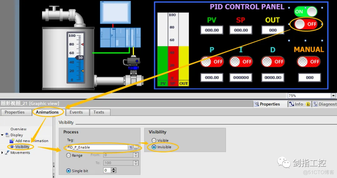
One invisible “Button” related with “Click” event;
一个不可见的“按钮”关联“单击”事件;
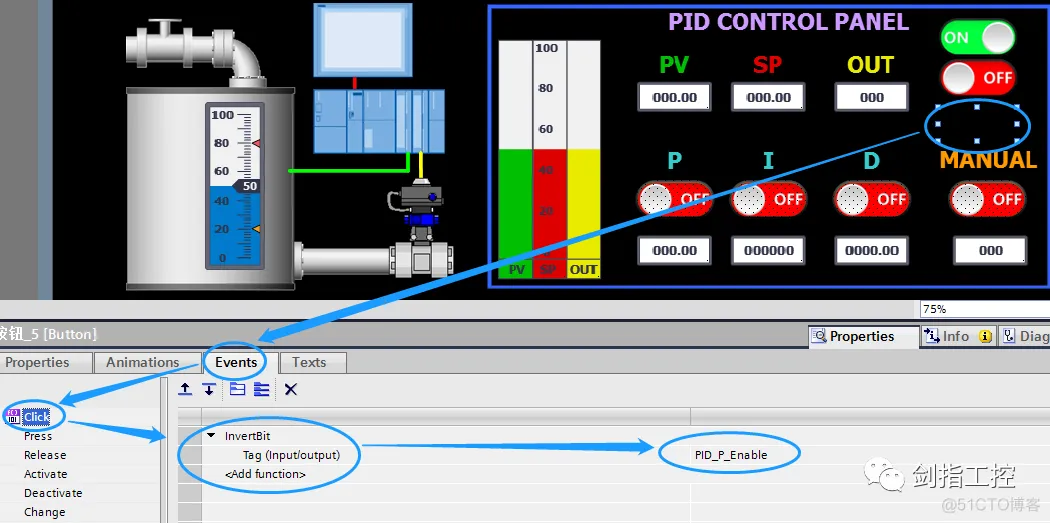
Make these three parts overlap, and set the button to be the top position;
将三个部分重叠,并将按钮设置为最上层;
7.Open the PLCSIM software, download the program and turn to Run, Start HMI simulation and test;
打开PLCSIM软件,下装程序并打到运行状态,启动人机界面仿真并开始测试;
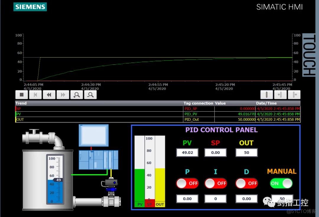
PID Controller set to Manual mode, and give the manual value, will see the PID output hold in value, and Controlled Object value (PV) increased as the inertial element (First-order process);
PID控制器设为手动模式,设定手动值,可以看到PID输出保持不变,被控对象的过程量持续增长表现为一个一阶惯性环节;
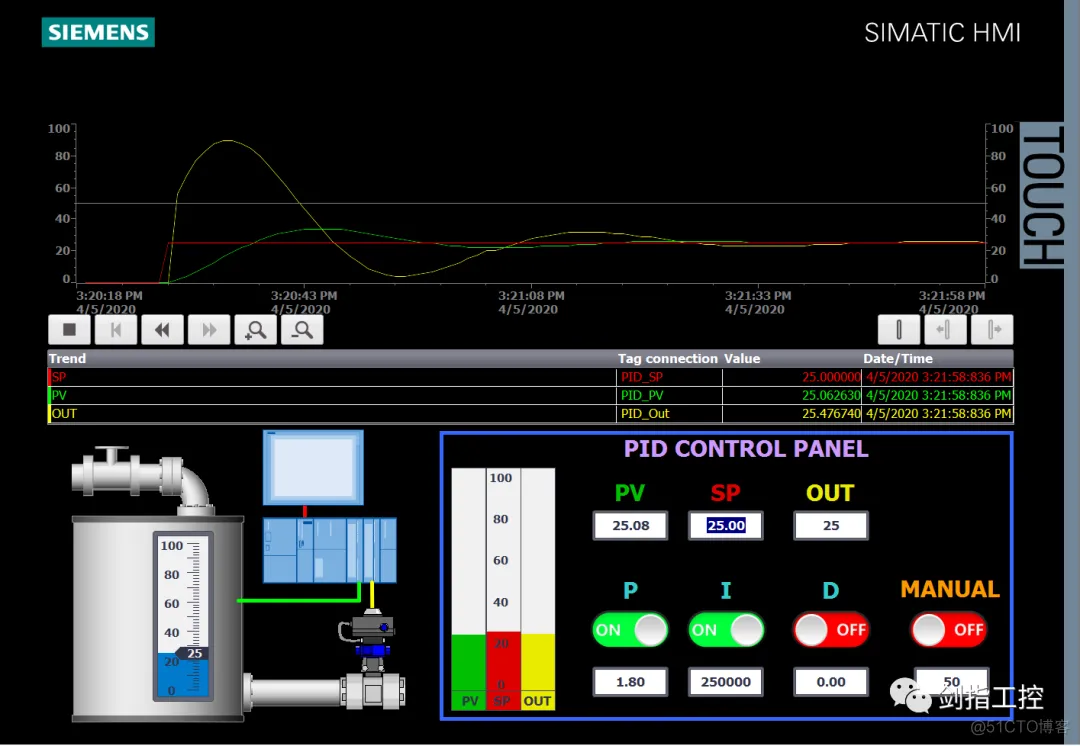
PID Controller set to Auto mode, set the “P, I, D” parameters and give the SP value, will see the Controlled Object response faster and follow the SP value;
将PID控制器设置为自动模式,设置“P, I, D”参数并给出SP值,会看到被控对象响应更快并跟随SP值;
Conclusion: 结语
For this case only provide to reader the way of Controlled Object simulation in PID control loop, and still have so many improvement parts such as:
本例仅提供给读者一个在PID控制回路中被控对象的仿真方法,仍然有许多地方可以改进例如:
P
免责声明:本文系网络转载或改编,未找到原创作者,版权归原作者所有。如涉及版权,请联系删